
This blog series is a part of the write-up assignments of my Real-Time Game Rendering class in the Master of Entertainment Arts & Engineering program at University of Utah. The series will focus on C++, Direct3D 11 API and HLSL.
In this post, I will introduce a simple directional light and an ambient light into my engine, and observe how that changes the look of the scene. I am also adding tangent and bi-tangent to the scene.
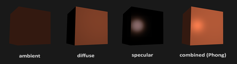
Diffuse Light
Diffuse lighting is one of the simplest lightings that we can have in a game. When a ray of light hits a surface, it might be reflected, absorbed, or release from the surface after a while. The latter one is the diffuse light. Diffuse lighting can be easily simulated by using the cosine value of the angle between the incident light and the surface normal. We can retrieve this value by taking the dot product of two vectors (assuming that they are already normalized).


Below shows the result of introducing diffuse lighting. I have tested it with hard edges (UV values are the same for a triangle’s vertices), and also soft edges (UV values of the vertices are independent of each other). The difference between soft edges and hard edges are significant and can be easily observed.

Green directional lighting

Ambient Light
In the videos shown in the above, you can see that the sides on the opposite side of the light are totally dark. This is because we don’t have ambient lighting in the scene right now. We can easily introduce some simple ambient lighting that is just a fixed value such as (0.2, 0.2, 0.2) to guarantee no place in the scene is absolutely dark.
Debugging
When we’re setting up the lighting and testing, sometimes it can be hard to determine which part of the pipeline is causing the scene to be lit incorrectly. In these cases, we can use the shader debugger provided by Visual Studio to step through our shader codes and even re-run the shading results quickly to see if it is fixed!

Normal and Emissive Map
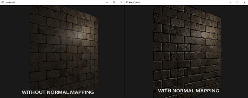
Next thing that I want to do is add a normal map and an emissive map to the pipeline. Using a normal map can give the mesh the illusion of having more details than it actually does.
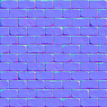
However, when we look at a normal map, it often appears to be pretty close to a blue-ish color. This is because the normal is shown in the tangent space, and the rgb channels map to xyz values. Since the normals are mostly pointing outward (+z axis), the blue channel gets the largest values. If we want to use the normal values from the normal maps, we’ll need to either convert them into the world space, or convert our lightings into the tangent space. Either way, we would need the tangent and bitangent values of the vertices.

I decided to convert the lightings direction with the inverse of a TBN matrix that I construct with the normal vector, the tangent vector, and the bitangent vector. Because the constructed matrix is orthonormal, we can simply take the transpose of it to be the same as its inverse. After transforming the light’s direction into the tangent space, we can pass it on to our fragment shader.
Inside our fragment shader, we sample the new normal vector from the normal map and convert the values from 0.0 ~ 1.0 to -1.0 ~ +1.0. Now we can calculate the diffuse lighting with the normal and the light’s direction both inside the tangent space!
The results of normal mapping is shown below, you can see that normal mapping adds a lot of extra detail onto the mesh, making the inscriptions look less like a flat surface!


Comparing to normal mapping, adding emissive to a mesh is a lot more straightforward. We can simply sample the rgb values from the emissive texture and add it to the final color output. The shader codes and the results are shown below.


