This blog series is a part of the write-up assignments of my Real-Time Game Rendering class in the Master of Entertainment Arts & Engineering program at University of Utah. The series will focus on C++, Direct3D 11 API and HLSL.
In this post, I will talk about how I switched to using BRDF in my lighting calculation to achieve physically-based rendering (PBR) in my rendering engine. I am also adding gloss map into the engine, but not metallic map for now.
Physically-Based Rendering
Comparing to the ad hoc shading approach that I previously used. PBR, which contains a collection of different render techniques, can generate results that are more physically-based, and therefore, realistic. It does not necessarily mean that it will look better, per se. But it does mean that it can provide a baseline that usually looks pretty good and allow us to have something with results closer to our expectation in real life to work with.
I am not gonna go into the details of the whole theory since there are many awesome documents and tutorials online. Such as Physically-Based Shading Models in Film and Games Production, Crafting Physically Motivated Shading Models for Game Development, and the tutorial on learnopengl.com.
A PBR lighting model needs to satisfy the 3 properties below.
- Be based on the microfacet model. (no surface is really flat in the microscope)
- Be energy preserving. (the total energy of lights leaving a surface cannot surpass the total energy of the light hitting the surface)
- Use a physically based bidirectional reflective distribution function (BRDF).
Reflectance Equation
To achieve a more physically-based shading result, instead of only considering an incoming light and one outgoing light from a surface, we actually need to take all incoming light onto a point p which contributes to the outgoing light that we see.
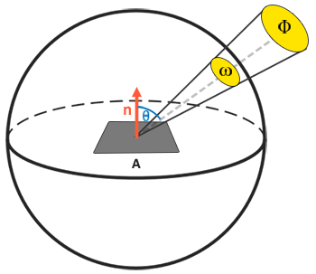
If we shrink the area A and the solid angle to be infinitely small, then we effectively translate the solid angle into a vector, and area A into a point p on a surface. By doing this, we can use radiance to calculate the per-fragment contribution of light rays. This is where the reflectance equation comes into place.
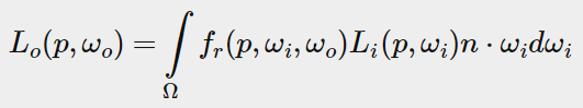
The fr symbol in the equation is known as the bidirectional reflective distribution (BRDF) function that scales or weighs the incoming radiance based on the surface’s material properties.
Bidirectional Reflective Distribution Function (BRDF)
The BRDF is an approximation of how much each individual light ray ωi contributes to the final reflected light of an opaque surface given its material properties. For a perfectly smooth surface (mirror, for example), the BRDF would return 0.0 for all incoming light rays except the one that has the same angle as the outgoing ray, at which BRDF will return 1.0.
Almost all real-time render pipelines use the BRDF known as the Cool-Torrance BRDF.
Specular BRDF
The specular part of the BRDF looks like this
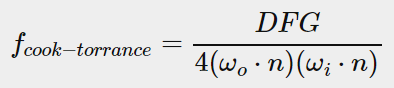
IT consists of three different functions. D for the distribution function, F for the Fresnel equation, and G for the geometry function.
- Normal distribution function: approximates the amount the surface’s microfacets are aligned to the halfway vector influenced by the roughness of the surface; this is the primary function approximating the microfacets.
- Geometry function: describes the self-shadowing property of the microfacets. When a surface is relatively rough the surface’s microfacets can overshadow other microfacets thereby reducing the light the surface reflects.
- Fresnel equation: The Fresnel equation describes the ratio of surface reflection at different surface angles.
Distribution Function
I am using normalized Blinn-Phong as my distribution function here. Basically, this equation determines how many microfacets’ normals are aligned with the half-angle vector.
- [(α + 2) / 2 * pi] * (n⋅h)α
Where α is the “glossiness” value in my engine, vector n is the normal vector at that fragment, and h vector is the light-view half vector.
Fresnel Equation
For the Fresnel effect, I am using Schlick’s approximation here. This will cause more light to be reflected at steeper angles.
- R0 + [(1 – R0) * (1 – (l⋅h))5]
Results
Now I have switched my rendering code into PBR, let’s take a look at how the bear in my game will react to different glossiness value. You can see that since now we added the energy preserving property into the equation, the brightness contributed by specular lighting and diffusing appears to add up to a fixed amount, which creates a more realistic look. I started with a higher glossiness and then lower it down in the video.
However, you may have noticed that I did not specifically talk about the geometry function term in the Cook-Torrace BRDF equation. This is because I am using a simpler version of estimation that cancels the geometry term out from the equation. Therefore, what I am showing here is only an estimation of PBR. In the future, I might add that term in along with roughness mapping so that I can achieve more realistic PBR!
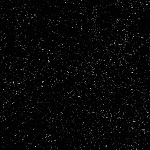
Gloss Map
Comparing to my rendering pipeline before, PBR has introduced some more texture maps into my engine. One of them is the gloss map, which will be used to replace the single glossiness value that I am currently using. In my engine, I use white to represent higher values while black is 0.
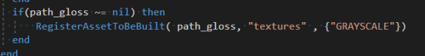
Since the gloss map will be grayscale and only contain one channel, I need to modify the assert builder to handle it appropriately.
When building the material, I will also register the gloss map to be built with argument “GRAYSCALE”. Inside the texture builder, I am using BC4 to compress the grayscale gloss map.
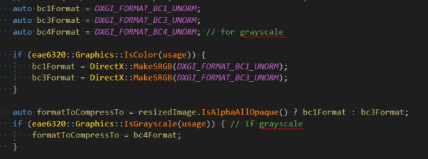
Grayscale gloss map compression
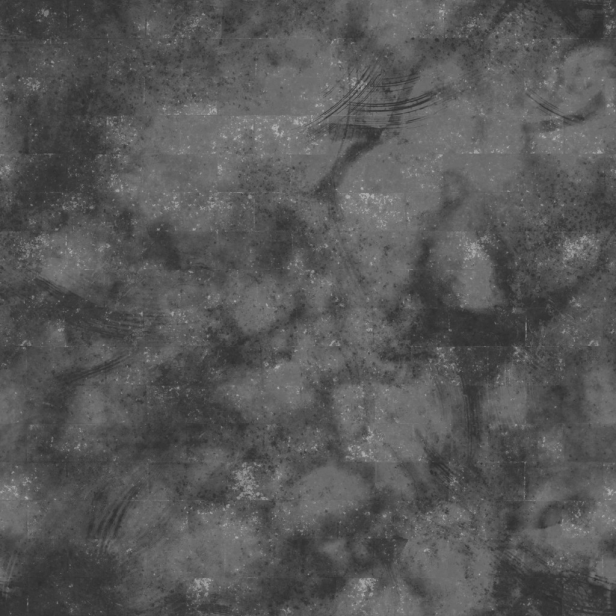
Now let’s take a look at how the gloss map can change the look of the meshes! Below shows the result of the marble material and terracotta tiles material.
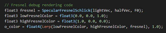
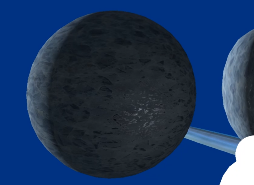
Fresnel Effect
While the Fresnel effect is really hard to observe, we can use simple debug rendering code to verify that it is working as expected. In the video below, red means high Fresnel value, and blue means low. You can see that for dielectric objects (except the first row), there is little to none Fresnel effect when the light and the camera is coming roughly at the same direction, while the Fresnel effect starting to show when the light vector and the view vector are on the opposite sides of the fragments.